VENTARIS N+ Die Kombination aus Nano+ und Ventaris

The combination of
Nano+ and Ventaris

Ventaris N+

The combination of Nano+ and Ventaris

Nano+ actuator head
  • Synchronous motor (24 VAC, 115 VAC, 230 VAC), alternatively 24 VDC motor
  • Metal body / cover
  • Robust industrial design
  • Expandable functions through numerous options
  • Failsafe option – moves to a safe position in case of a power outage
  • Adjustment via fixable aluminium control cams

Actuating force

1000...6000

N

Actuating time

0.1...1.3

mm/s

Technical data Nano+
Protection typeIP 65
Ambient temperature– 15° C…+60° C (optionally – 40° C…+80° C)
HousingPowder-coated die-cast aluminium
Gear unitMetal
CoverAluminium
Hand wheelExternal (optional)
Position indicatorMechanical
Supply voltage230 VAC; optionally 115 VAC, 24 VAC, 24 VDC
Additional switches2 or 4, optional
PotentiometerOptional
Duty cycle100 %
Connection3 cable entries M16x1.5
Switch offAluminium control cam, micro-switch
MaintenanceMaintenance-free
Actuation3-point step (optional positioner)
Type Ventaris N+
Actuating force (N)10001000100010001000200020002000200020003000300030003000
Actuating time (mm/s)0,10,30,50,81,30,10,30,50,81,30,10,30,50,8
Actuating force (N)30004000400040004000400050005000500050006000600060006000
Actuating time (mm/s)1,30,10,30,50,81,30,10,30,50,70,10,30,50,7

Other actuating times on request
Ventaris N+ – Options

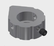
Cam profiles

  • 330° / 180°
  • With set screw for securing position

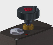
Hand wheel

  • Automatic disconnect
  • Not co-rotating

Mechanical position indicator

  • Freely adjustable

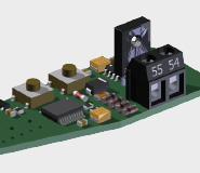
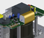
Current output (additional PCB)

  • Position feedback 4 – 20 mA

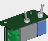
Service switch (standard with DC)

  • Manual / automatic operation (switch)
  • Left hand / right hand rotation (button)
  • Integrated in actuator

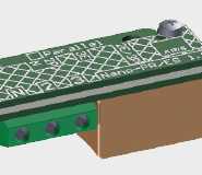
Parallel relay / single-wire control (AC)

  • AC-relay
  • Completely wired
  • Operating voltage = motor voltage
  • Parallel connection of multiple actuators

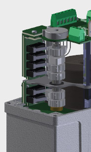
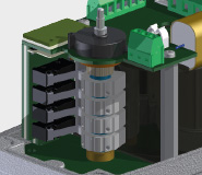
Two or four additional auxiliary switches

  • Adjustment via control cams that can be adjusted without tools
  • Different control cam forms enable different functions of the auxiliary path switches
  • High switching reliability due to spacer between the PCB and the control cam shaft

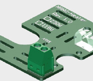
Heating

  • For heating the interior of the actuator to prevent condensation of water

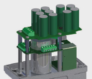
Fail-safe

  • Energy storage
  • Moves to pre-defined position in case of power outage
  • Charge time <3 minutes
  • Integrated in the actuator
  • Moves at control speed or high speed
  • 24 VDC

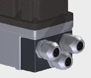
Cable entry adapter

  • For cable gland 3xM20 (instead of 3xM16)
  • Cable entry from front
  • Anodised aluminium

Potentiometer

Standard

  • 1 kΩ/10 kΩ
  • Position feedback

PMR-Nano (AC)

Power supply:

  • 230 V ±10%, 50/60 Hz
  • Special voltages / frequencies on request

Reference input:

  • 0 (4) to 20 mA (DC), optionally 0 (2) to 10 V
  • Load 250 Ω, overload protection 25 mA
  • Reverse voltage protection up to – 25 mA
  • Resolution 10 bit

Actual output:

  • Fixed limits: 0 or 4 – 20 mA
  • (Optionally 0 or 2 – 10 V)
  • Current sink, max. load 500 Ω
  • Resolution 10 bit